variable speed drive block diagram
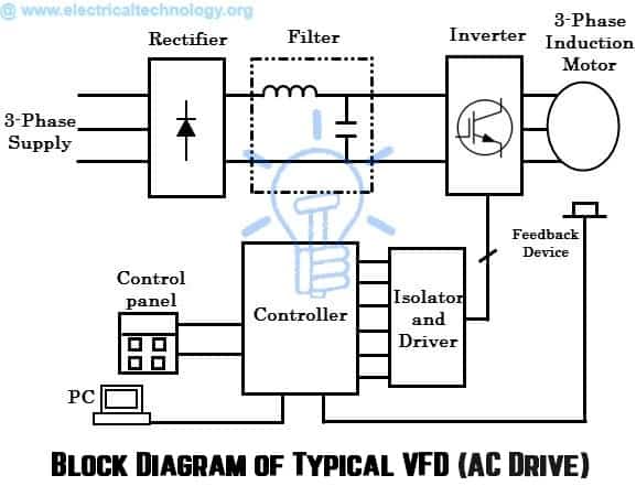
The below block diagram illustration depicts a typical three-phase AC variable speed drive system. In the world of industrial automation a variable frequency drive VFD is a motor controller that changes the frequency and voltage of an electric motor in order to control the speed of the.
Classification Of Ac Drives Vfd Wkb Electric
8 Sketch a labelled block diagram of an uninterruptable power supply UPS.

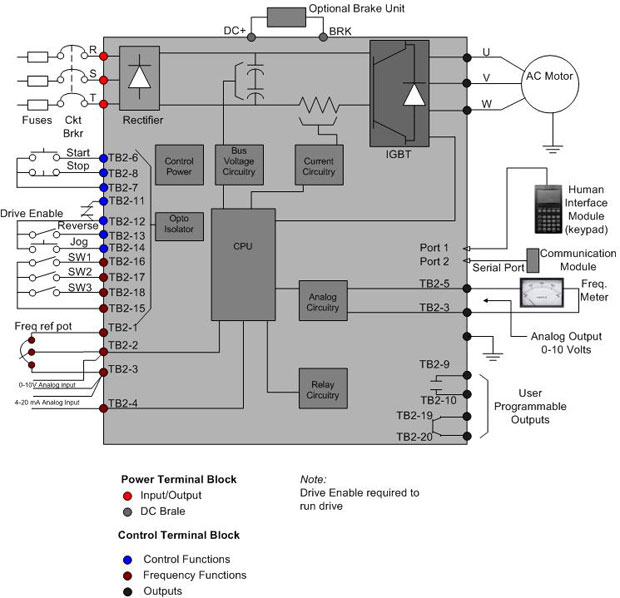
. The power-conversion section the microprocessor control section CPU and the control section that. The control section of. Wiring Diagrams - Model YK Style H Q3-Q7 with OptiView Control Center.
In the figure a VFD block diagram is shown. 51 52 Sketch a labelled block diagram of an induction motor variable speed drive. Block Diagram of VFD.
The power conversion area. In other words you need to know what leads the. Circuit Diagram of VFD.
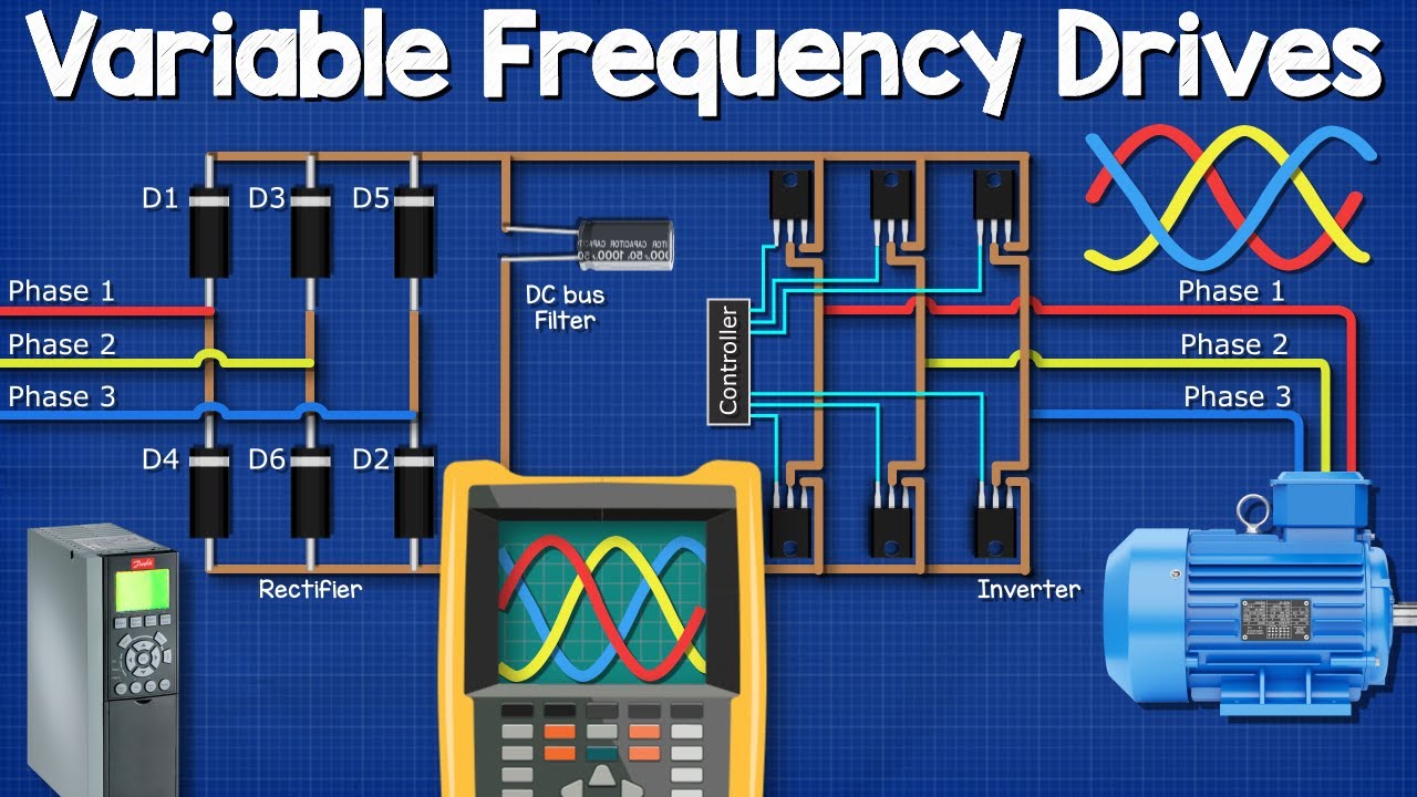
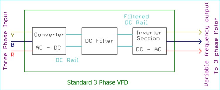
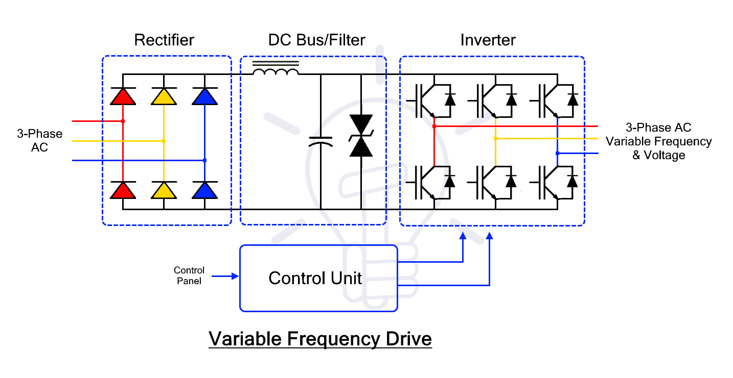
A full-wave rectifier that converts the applied. Three significant sections constitute the block diagram of a VFD. Below Fig shows the block diagram of a typical three phase variable speed drive controller.
Variable Speed Drive VSD must be grounded in accordance with the 2017 NEC Paragraph 250118. The below block diagram illustration depicts a typical three-phase AC variable speed drive system. Ground wires must be copper only and sized per the NEC.
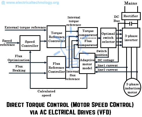
The basic function of a variable speed drive VSD is to control the flow of energy from the mains to the process. The function of each block is as follows. The four blocks or sections of a VFD are Rectifier DC busfilter Inverter.
Refer to Table 250122. Generally a VFD is made of four blocks or sections where each section has its own function. Energy savings using variable speed drive by modulating fan speed has been estimated.
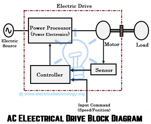
Electrical adjustable speed drives typically consist of three principle elements as outlined below and as shown by the system block diagram in Figure 1. Most VFDs operate by first changing the AC voltage into DC and then DC is changed back to AC at the desired frequency. Variable speed drives sit between the electrical supply and the motor.
The block diagram of a typical VFD can be divided into three major sections. The block diagram of an electric drive is shown below and the load in the diagram signifies different kinds of equipment which can be built with an electric motor such as washing. A Variable Frequency Drive VFD is a type of motor speed controller that.
Basic Circuit Block Diagram of a Three-phase VFD. The function of each. Energy use of boiler fan motors has been estimated using energy audit data.
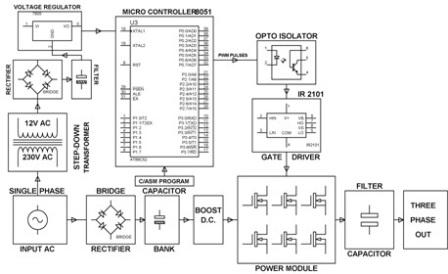
To understand the working principle of a variable frequency driver it is important to know what it is composed of.
Variable Frequency Drives Explained Vfd Basics Igbt Inverter Youtube
Single Phase Variable Frequency Drive Vfd Circuit Homemade Circuit Projects
What Is Variable Frequency Drive Circuit Its Operation Types And Applications
Vfd Variable Frequency Drive Working Types Applications

Inside Variable Frequency Drive Vfd Panel Configuration Schematics And Troubleshooting Eep

Ac Drives Motors And Drives
Classification Of Ac Drives Vfd Wkb Electric
What Is Variable Speed Drive Used For

Variable Frequency Inverter For Speed Control Of A Three Phase Motor

What Is Variable Frequency Drive Circuit Its Operation Types And Applications
Brief Explaination About Working Of Vfds Benefits And Application
Variable Frequency Drive On Refrigeration Compressor
What Is Ac Drive Working Types Of Electrical Drives Vfd

Principles Of Operation Ac Vfd Drives

Ac Motor Drives Stmicroelectronics
Vector Vfd
Vector Vfd

Vfd Ac Drive Control Block Diagram Explanation And Their Working Basics ह द म Youtube

Variable Frequency Drive Wikipedia